POOL PERMIT REQUIREMENTS
No pool may be used until a Final Inspection has been done and PASSED and a C/O has been issued. In order to pass the Final Inspection, a proper pool barrier MUST be in place at the time of inspection. Proof of an existing fence that qualifies as a proper pool barrier OR proof that you have contracted to have a barrier installed is REQUIRED BEFORE a permit is issued.
PLEASE READ the following:
- Pool Barrier Requirements - All
- OnGround / Storable Pool Requirements
- Above Ground Code Compliant Pool Electrical Guide. (PDF)
Print This Entire Page (13 pages)
Print the Barrier Regulations Only (4 page PDF)
Print the On Ground Pool Regulations Only (11 pages PDF)
Print the Above Ground Code Compliant Pool Electrical Guide (1 page PDF)
PENNSYLVANIA SWIMMING POOL AND SPA CODE 2018
Section 305 Barrier Requirements
305.1 General
The provisions of this section shall apply to the design of barriers for restricting entry into areas having pools and spas. Where spas or hot tubs are equipped with a lockable safety cover complying with ASTM F1346 and swimming pools are equipped with a powered safety cover that complies with ASTM F1346, the areas where those spas, hot tubs or pools are located shall not be required to comply with Sections 305.2 through 305.7.
305.2 Outdoor Swimming Pools and Spas
Outdoor pools and spas and indoor swimming pools shall be surrounded by a barrier that complies with Sections 305.2.1 through 305.7.
305.2.1 Barrier Height and Clearances
Barrier heights and clearances shall be in accordance with all of the following:
- The top of the barrier shall be not less than 48 inches (1219 mm) above grade where measured on the side of the barrier that faces away from the pool or spa. Such height shall exist around the entire perimeter of the barrier and for a distance of 3 feet (914 mm) measured horizontally from the outside of the required barrier.
- The vertical clearance between grade and the bottom of the barrier shall not exceed 2 inches (51 mm) for grade surfaces that are not solid, such as grass or gravel, where measured on the side of the barrier that faces away from the pool or spa.
- The vertical clearance between a surface below the barrier to a solid surface, such as concrete, and the bottom of the required barrier shall not exceed 4 inches (102 mm) where measured on the side of the required barrier that faces away from the pool or spa.
- Where the top of the pool or spa structure is above grade, the barrier shall be installed on grade or shall be mounted on top of the pool or spa structure. Where the barrier is mounted on the top of the pool or spa, the vertical clearance between the top of the pool or spa and the bottom of the barrier shall not exceed 4 inches (102 mm).
305.2.2 Openings
Openings in the barrier shall not allow passage of a 4-inch-diameter (102 mm) sphere.
305.2.3 Solid Barrier Surfaces
Solid barriers that do not have openings shall not contain indentations or protrusions that form handholds and footholds, except for normal construction tolerances and tooled masonry joints.
305.2.4 Mesh Fence as a Barrier
Mesh fences, other than chain link fences in accordance with Section 305.2.7, shall be installed in accordance with the manufacturer's instructions and shall comply with the following:
- The bottom of the mesh fence shall be not more than 1 inch (25 mm) above the deck or installed surface or grade.
- The maximum vertical clearance from the bottom of the mesh fence and the solid surface shall not permit the fence to be lifted more than 4 inches (102 mm) from grade or decking.
- The fence shall be designed and constructed so that it does not allow passage of a 4-inch (102 mm) sphere under any mesh panel. The maximum vertical clearance from the bottom of the mesh fence and the solid surface shall be not greater than 4 inches (102 mm) from grade or decking.
- An attachment device shall attach each barrier section at a height not lower than 45 inches (1143 mm) above grade. Common attachment devices include, but are not limited to, devices that provide the security equal to or greater than that of a hook-and-eye-type latch incorporating a spring-actuated retaining lever such as a safety gate hook.
- Where a hinged gate is used with a mesh fence, the gate shall comply with Section 305.3.
- Patio deck sleeves such as vertical post receptacles that are placed inside the patio surface shall be of a nonconductive material.
- Mesh fences shall not be installed on top of onground residential pools.
305.2.5 Closely Spaced Horizontal Members
Where the barrier is composed of horizontal and vertical members and the distance between the tops of the horizontal members is less than 45 inches (1143 mm), the horizontal members shall be located on the pool or spa side of the fence. Spacing between vertical members shall not exceed 1 3/4 inches (44 mm) in width. Where there are decorative cutouts within vertical members, spacing within the cutouts shall not exceed 1 3/4 inches (44 mm) in width.
305.2.6 Widely Spaced Horizontal Members
Where the barrier is composed of horizontal and vertical members and the distance between the tops of the horizontal members is 45 inches (1143 mm) or more, spacing between vertical members shall not exceed 4 inches (102 mm). Where there are decorative cutouts within vertical members, the interior width of the cutouts shall not exceed 1 3/4 inches (44 mm).
305.2.7 Chain Link Dimensions
The maximum opening formed by a chain link fence shall be not more than 1 3/4 inches (44 mm). Where the fence is provided with slats fastened at the top and bottom that reduce the openings, such openings shall be not greater than 1 3/4 inches (44 mm).
305.2.8 Diagonal Members
Where the barrier is composed of diagonal members, the maximum opening formed by the diagonal members shall be not greater than 1 3/4 inches (44 mm). The angle of diagonal members shall be not greater than 45 degrees (0.79 rad) from vertical.
305.2.9 Clear Zone
There shall be a clear zone of not less than 36 inches (914 mm) between the exterior of the barrier and any permanent structures or equipment such as pumps, filters and heaters that can be used to climb the barrier.
305.2.10 Poolside Barrier Setbacks
The pool or spa side of the required barrier shall be not less than 20 inches (508 mm) from the water's edge.
305.3 Gates
Access gates shall comply with the requirements of Sections 305.3.1 through 305.3.3 and shall be equipped to accommodate a locking device. Pedestrian access gates shall open outward away from the pool or spa, shall be self-closing and shall have a self-latching device.
305.3.1 Utility or Service Gates
Gates not intended for pedestrian use, such as utility or service gates, shall remain locked when not in use.
305.3.2 Double or Multiple Gates
Double gates or multiple gates shall have not fewer than one leaf secured in place and the adjacent leaf shall be secured with a selflatching device. The gate and barrier shall not have openings larger than 1/2 inch (12.7 mm) within 18 inches (457 mm) of the latch release mechanism. The self-latching device shall comply with the requirements of Section 305.3.3.
305.3.3 Latches
Where the release mechanism of the self-latching device is located less than 54 inches (1372 mm) from grade, the release mechanism shall be located on the pool or spa side of the gate not less than 3 inches (76 mm) below the top of the gate, and the gate and barrier shall not have openings greater than 1/2 inch (12.7 mm) within 18 inches (457 mm) of the release mechanism.
305.4 Structure Wall as a Barrier
Where a wall of a dwelling or structure serves as part of the barrier and where doors or windows provide direct access to the pool or spa through that wall, one of the following shall be required:
- Operable windows having a sill height of less than 48 inches (1219 mm) above the indoor finished floor and doors shall have an alarm that produces an audible warning when the window, door or their screens are opened. The alarm shall be listed and labeled as a water hazard entrance alarm in accordance with UL 2017. In dwellings or structures not required to be Accessible units, Type A units or Type B units, the operable parts of the alarm deactivation switches shall be located 54 inches (1372 mm) or more above the finished floor. In dwellings or structures required to be Accessible units, Type A units or Type B units, the operable parts of the alarm deactivation switches shall be located not greater than 54 inches (1372 mm) and not less than 48 inches (1219 mm) above the finished floor.
- A safety cover that is listed and labeled in accordance with ASTM F1346 is installed for the pools and spas.
- An approved means of protection, such as self-closing doors with self-latching devices, is provided. Such means of protection shall provide a degree of protection that is not less than the protection afforded by Item 1 or 2.
305.5 Onground Residential Pool Structure as a Barrier
An onground residential pool wall structure or a barrier mounted on top of an onground residential pool wall structure shall serve as a barrier where all of the following conditions are present:
- Where only the pool wall serves as the barrier, the bottom of the wall is on grade, the top of the wall is not less than 48 inches (1219 mm) above grade for the entire perimeter of the pool, the wall complies with the requirements of Section 305.2 and the pool manufacturer allows the wall to serve as a barrier.
- Where a barrier is mounted on top of the pool wall, the top of the barrier is not less than 48 inches (1219 mm) above grade for the entire perimeter of the pool, and the wall and the barrier on top of the wall comply with the requirements of Section 305.2.
- Ladders or steps used as means of access to the pool are capable of being secured, locked or removed to prevent access except where the ladder or steps are surrounded by a barrier that meets the requirements of Section 305.
- Openings created by the securing, locking or removal of ladders and steps do not allow the passage of a 4-inch (102 mm) diameter sphere.
- Barriers that are mounted on top of onground residential pool walls are installed in accordance with the pool manufacturer's instructions.
305.6 Natural Barriers
In the case where the pool or spa area abuts the edge of a lake or other natural body of water, public access is not permitted or allowed along the shoreline, and required barriers extend to and beyond the water's edge not less than 18 inches (457 mm), a barrier is not required between the natural body of water shoreline and the pool or spa.
305.7 Natural Topography
Natural topography that prevents direct access to the pool or spa area shall include but not be limited to mountains and natural rock formations. A natural barrier approved by the governing body shall be acceptable provided that the degree of protection is not less than the protection afforded by the requirements of Sections 305.2 through 305.5.
Section 7 - Onground or Storable Residential Swimming Pools
701.2 General
In addition to the requirements of this chapter, onground storable residential swimming pools shall comply with the requirements of Chapter 3.
701.3 Floor Slopes
Floor slopes shall be uniform and in accordance with Sections 701.3.1 through 701.3.4.
701.3.1 Shallow End
The slope of the floor from the shallow end wall towards the deep area shall not exceed 1 unit vertical in 7 units horizontal (14-percent slope) to the point of the first slope change.
701.3.2 Transition
The slope of the floor from the point of the first slope change towards the deepest point shall not exceed 1 unit vertical in 3 units horizontal (33-percent slope).
701.3.3 Adjacent
The slope adjacent to the shallow area shall not exceed 1 unit vertical in 3 units horizontal (33-percent slope) and the slope adjacent to the side walls shall not exceed 1 unit vertical in 1 unit horizontal (100-percent slope).
701.3.4 Change Point
The point of the first slope change shall be defined as the point at which the shallow area slope exceeds 1 unit vertical in 7 units horizontal (14-percent slope) and is not less than 6 feet (1889 mm) from the shallow end wall of the pool.
701.4 Identification
For onground storable residential pools with a vinyl liner, the manufacturer's name and the liner identification number shall be affixed to the liner. For onground storable residential pools without a liner, the manufacturer's name and identification number shall be affixed to the exterior of the pool structure.
701.5 Installation
Onground storable pools shall be installed in accordance with the manufacturer's instructions.
Section 702 Ladders and Stairs
702.1 Ladders and Stairs
Pools shall have a means of entry and exit consisting of not less than one ladder or a ladder and staircase combination.
702.2 Type A and Type B Ladders
Type A, double access, and Type B, limited access, A-frame ladders shall comply with Sections 702.2.1 through 702.2.7. See Figure 702.2.
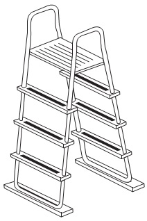
FIGURE 702.2 TYPICAL A-FRAME LADDER, TYPES A AND B
702.2.1 Barrier Required
Ladders in the pool shall have a physical barrier to prevent children from swimming through the riser openings or behind the ladder. Exception: Barriers for ladders shall not be required where the ladder manufacturer provides a certification statement that the ladder complies with the ladder entrapment test requirements of APSP 4.
702.2.2 Platform
Where an A-frame ladder has a platform between the handrails, the platform shall have a width of not less than 12 inches (305 mm) and a length of not less than 12 inches (305 mm). The platform shall be at or above the highest ladder tread. The walking surface of the platform shall be slip resistant.
702.2.3 Handrails or Handholds
A-frame ladders shall have two handrails or handholds that serve all treads. The height of the handrails and handholds shall be not less than 20 inches (508 mm) above the platform or uppermost tread, whichever is higher.
702.2.4 Diameter
The outside diameter of handrails and handholds shall be not less than 1 inch (25 mm) and not greater than 1.9 inches (48 mm).
702.2.5 Clear Distance
The clear distance between ladder handrails shall be not less than a space of 12 inches (305 mm).
702.2.6 Treads
Ladder treads shall have a horizontal uniform depth of not less than 2 inches (51 mm).
702.2.7 Riser Height
Risers, other than the bottom riser, shall be of uniform height that is not less than 7 inches (178 mm) and not greater than 12 inches (305 mm). The bottom riser height shall be not less than 7 inches (178 mm) and not greater than 12 inches (305 mm). The vertical distance from the platform or top of the pool structure to the uppermost tread shall be the same as the uniform riser heights.
702.3 Type C Staircase Ladders (Ground to Deck)
Type C staircase ladders shall comply with Sections 702.3.1 through 702.3.6. See Figure 702.3.
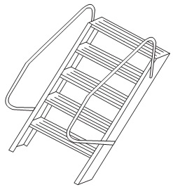
FIGURE 702.3 TYPICAL STAIRCASE LADDER, TYPE C
702.3.1 Handrails or Handholds
Staircase ladders shall have not less than two handrails or handholds that serve all treads. The height of the handrails and handholds shall be not less than 20 inches (508 mm) above the platform or uppermost tread, whichever is higher.
702.3.2 Diameter
The outside diameter of handrails and handholds shall be not less than 1 inch (25 mm) and not greater than 1.9 inches (48 mm).
702.3.3 Treads
Ladder treads shall have a horizontal uniform depth of not less than 4 inches (102 mm).
702.3.4 Riser Height
Risers, other than the bottom riser, shall be of uniform height that is not less than 7 inches (178 mm) and not greater than 12 inches (305 mm). The bottom riser height shall be not less than 7 inches (178 mm) and not greater than 12 inches (305 mm). The vertical distance from the platform or top of the pool structure to the uppermost tread shall be the same as the uniform riser heights.
702.3.5 Top Step
The top step of a staircase ladder shall be flush with the deck or 7 inches (178 mm) to 12 inches (305 mm) below the deck level.
702.3.6 Width
Steps shall have a minimum unobstructed width of 19 inches (483 mm) between the side rails.
702.4 Type D In-Pool Ladders
Type D in-pool ladders shall be in accordance with Sections 702.4.1 through 702.4.7. See Figure 702.4.
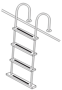
FIGURE 702.4 TYPICAL IN-POOL LADDER, TYPE D
702.4.1 Clearance
There shall be a clearance of not less than 3 inches (76 mm) and not greater than 6 inches (152 mm) between the pool wall and the ladder.
702.4.2 Handrails or Handholds
Ladders shall be equipped with two handrails or handholds that extend above the platform or deck not less than 20 inches (508 mm).
702.4.3 Clear Distance
The clear distance between ladder handrails shall be not less than 12 inches (305 mm).
702.4.4 Diameter
The outside diameter of handrails and handholds shall be not less than 1 inch (25 mm) and not greater than 1.9 inches (48 mm).
702.4.5 Riser Height
Risers, other than the bottom riser, shall be of uniform height that is not less than 7 inches (178 mm) and not greater than 12 inches (305 mm). The bottom riser height shall be not less than 7 inches (178 mm) and not greater than 12 inches (305 mm).
702.4.6 Top Tread
The vertical distance from the pool coping, deck, or step surface to the uppermost tread shall be not less than 7 inches (178 mm) and not greater than 12 inches (305 mm) and uniform with other riser heights.
702.4.7 Tread Depth
Ladder treads shall have a horizontal uniform depth of not less than 2 inches (51 mm).
702.5 Type E Protruding In-Pool Stairs
Type E protruding in-pool stairs shall be in accordance with Sections 702.5.1 through 702.5.7. See Figure 702.5
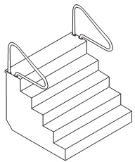
FIGURE 702.5 TYPICAL IN-POOL STAIRCASE TYPES, E AND F
702.5.1 Barrier Required
In-pool stairs shall have a physical barrier to prevent children from swimming through the riser openings or behind the in-pool stairs.
702.5.2 Handrails or Handholds
In-pool stairs shall be equipped with not less than one handrail or handhold that serves all treads with a height of not less than 20 inches (508 mm) above the platform or uppermost tread, whichever is higher.
702.5.3 Removable Handrails
Where handrails are removable, they shall be installed such that they cannot be removed without the use of tools.
702.5.4 Leading Edge Distance
The leading edge of handrails shall be 18 inches (457 mm) ± 3 inches (± 76 mm), horizontally from the vertical plane of the bottom riser.
702.5.5 Diameter
The outside diameter of handrails and handholds shall be not less than 1 inch (25 mm) and not greater than 1.9 inches (48 mm).
702.5.6 Tread Width and Depth
Treads shall have an unobstructed horizontal depth of not less than 10 inches (254 mm) and an unobstructed surface area of not less than 240 square inches (0.15 m2).
702.5.7 Uniform Riser Height
Risers, other than the bottom riser, shall be of uniform height that is not less than 7 inches (178 mm) and not greater than 12 inches (305 mm). The bottom riser height shall be not less than 7 inches (178 mm) and not greater than 12 inches (305 mm). The vertical distance from the pool coping, deck or step surface to the uppermost tread of the stairs shall be the same as the uniform riser heights.
702.6 Type F Recessed In-Pool Stairs
Type F recessed in-pool stairs shall be in accordance with Sections 702.6.1 through 702.6.7. See Figure 702.5.
702.6.1 Barrier Required
In-pool stairs shall have a physical barrier to prevent children from swimming through the riser openings or behind the in-pool stairs.
702.6.2 Handrails or Handholds
In-pool stairs shall be equipped with not less than one handrail or handhold that serves all treads with a height of not less than 20 inches (508 mm) above the platform or uppermost tread, whichever is higher.
702.6.3 Removable Handrails
Where handrails are removable, they shall be installed such that they cannot be removed without the use of tools.
702.6.4 Leading Edge Distance
The leading edge of handrails shall be 18 inches (457 mm) ± 3 inches (± 76 mm), horizontally from the vertical plane of the bottom riser.
702.6.5 Diameter
The outside diameter of handrails and handholds shall be not less than 1 inch (25 mm) and not greater than 1.9 inches (48 mm).
702.6.6 Tread Width and Depth
Treads shall have an unobstructed horizontal depth of not less than 10 inches (254 mm) at all points and an unobstructed surface area of not less than 240 square inches (0.15 m2).
702.6.7 Uniform Riser Height
Risers, other than the bottom riser, shall be of uniform height that is not less than 7 inches (178 mm) and not greater than 12 inches (305 mm). The bottom riser height shall be not less than 7 inches (178 mm) and not greater than 12 inches (305 mm). The vertical distance from the pool coping, deck or step surface to the uppermost tread of the stairs shall be the same as the uniform riser heights.
Section 703 Decks
703.1 General
Decks provided by the pool manufacturer shall be installed in accordance with the manufacturer's instructions. Decks fabricated on-site shall be in accordance with the International Residential Code.
703.2 Cantilevered
The top surface of a cantilevered deck shall be not greater than 1 inch (25 mm) higher than the top of the pool wall. See Figure 703.4 below. The top surface of a noncantilevered deck shall be not higher than the top of the pool wall.
703.3 No Gaps
Decks that are installed flush with the top rail of the pool shall have all gap openings between the deck and top rails closed-off or capped.
703.4 Extension Over Pool
Where a deck extends inside the top rail of the pool, it shall extend not more than 3 inches (76 mm) beyond the inside of the top rail of the pool in accordance with Figure 703.4 and shall have a smooth finish.

For SI: 1 inch = 25.4 mm. FIGURE 703.4 TYPICAL CANTILEVERED DECK SUPPORT
703.5 Slip Resistant
The deck walking surface shall be slip resistant.
703.6 Walk-Around Decks
Walk-around decks shall have a level walking surface of not less than 15 inches (381 mm) in width, as measured from the inside edge of the pool top rail to the outside of the pool walk-around. See Figure 703.6.
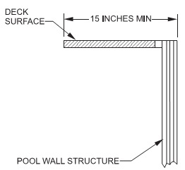
For SI: 1 inch = 25.4 mm. FIGURE 703.6 WALK-AROUND DECK WIDTH
Section 704 Circulation System
704.1 General
A circulation system consisting of pumps, hoses, tubing, piping, return inlets, suction outlets, filters and other related equipment that provides for the circulation of water throughout the pool shall be located so that such items cannot be used by young children as a means of access to the pool.
704.2 Installation and Support
Circulation equipment shall be installed, mounted and supported in accordance with the manufacturer's instructions.
704.3 Draining the System
In climates subject to freezing, circulation system equipment shall be designed and fabricated to drain the pool water from the equipment and exposed piping, by removal of drain plugs and manipulating valves or by other methods in accordance with the manufacturer's instructions.
704.4 Turnover
A pump including a motor shall be provided for circulation of the pool water. The equipment shall be sized to provide a turnover of the pool water not less than once every 12 hours. The system shall be designed to provide the required turnover rate based on the manufacturer's specified maximum flow rate of the filter, with a clean media condition of the filter. The system flow shall not exceed the filter manufacturer's maximum filter flow rate.
704.5 Piping and Fittings
The process piping of the circulation system, including but not limited to hoses, tubing, piping, and fittings, shall be made of nontoxic material and shall be capable of withstanding an internal pressure of not less than 1 1/2 times the rated pressure of the pump. Piping on the suction side of the pump shall not collapse when flow into such piping is blocked.
704.6 Filters
Pressure-type filters shall have an automatic internal means or a manual external means to relieve accumulated air pressure inside the filter tank. Filter tanks composed of upper and lower tank lids that are held in place by a perimeter clamp shall have a perimeter clamp that provides for a slow and safe release of air pressure before the clamp disengages the lids.
704.6.1 Automatic Internal Air Relief
Filter tanks incorporating an automatic internal air relief as the principal means of air release shall be designed with a means to provide for a slow and safe release of pressure.
704.6.2 Separation Tank
A separation tank used in conjunction with a filter tank shall have a manual air release or the tank shall be designed to provide for a slow and safe release of pressure when the tank is opened.
704.7 Pumps
Pool pumps shall be tested and certified by a nationally recognized testing laboratory in accordance with UL 1081.
704.7.1 Cleanable Strainer
Where a pressure-type filter is installed, a cleanable strainer or screen that captures materials such as solids, debris, hair and lint shall be provided upstream of the circulation pump.
704.7.2 Accessible Pumps and Motors
Pumps and motors shall be accessible for inspection and service in accordance with the pump and motor manufacturer's instructions.
704.7.3 Pump Shutoff Valves
An accessible means of shut off of the suction and discharge piping for the pump shall be provided for maintenance and removal of the pump.
704.8 Outlets and Return Inlets
Outlets or suction outlets and return inlets shall be provided and arranged to produce uniform circulation of water so that sanitizer residual is maintained throughout the pool. Where installed, submerged suction outlets shall conform to APSP 16.
704.9 Surface Skimmer Systems
The surface skimming system provided shall be designed and constructed to skim the pool surface where the water level is maintained between the minimum and maximum fill level of the pool.
704.9.1 Coverage Where Used as a Sole Outlet
Where surface skimmers are used as the only pool water outlet system, not less than one skimmer shall be provided for each 800 square feet (74.3 m2), or fraction thereof, of the water surface area.
704.9.2 Coverage Where Used in Combination With Other Outlets
Where surface skimmers are not the only outlet for pool water, they shall be considered to cover only that fraction of the 800 square feet (74.3 m2).
704.9.3 Location and Venting
Skimmers shall be equipped with a vent that serves as a vacuum break.
Section 705 Safety Signs
705.1 Signs to Be Installed Prior to Final Inspection
Safety signage such as "NO DIVING" signs and other safe use instruction signs that are provided by the pool and ladder manufacturer shall be posted in accordance with the manufacturer's instructions prior to final inspection.
705.2 Safety Signs for Ladders
Safety signage for ladders shall be in accordance with Sections 705.2.1 through 705.2.3.2.
705.2.1 A-Frame Ladders
Safety signage for A-frame ladders shall be in accordance with Sections 705.2.1.1 through 705.2.1.4.1. The words on the signage shall be readable by persons standing in the pool and standing outside of the pool as applicable for the required location of each sign.
705.2.1.1 No Diving Warning
A-frame ladders shall have the following words posted on the in-pool side of the ladder and on the pool entry side of the ladder: "NO DIVING." The location of the words shall be above the elevation of the design water level of the pool.
705.2.1.2 Entrapment Warning
A-frame ladders shall have the following words posted on the pool side of the ladder: "TO PREVENT ENTRAPMENT OR DROWNING DO NOT SWIM THROUGH, BEHIND, OR AROUND LADDER."
705.2.1.3 Type A, A-Frame Ladders
Type A double access A-frame ladders shall have the following words posted on the ladder: "REMOVE AND SECURE LADDER WHEN POOL IS NOT OCCUPIED."
705.2.1.4 Type B, A-Frame Ladders
Type B limited access A-frame ladders shall have the following words posted on the ladder: "SECURE LADDER WHEN POOL IS NOT OCCUPIED."
705.2.1.4.1 Swing Up or Slide Up Secured Ladders
Type B limited access A-frame ladders that utilize swing-up or slide-up sections for limiting access to the pool shall have the following words posted on the ladder as applicable for the type of securing method:
- "WHEN POOL IS NOT OCCUPIED, SWING UP AND SECURE"
- "WHEN POOL IS NOT OCCUPIED, LIFT OFF"
- "WHEN POOL IS NOT OCCUPIED, SLIDE UP AND SECURE"
705.2.2 Type C Staircase Ladders
Type C staircase ladders that swing up to limit access to the pool or that are removed to limit access to the pool shall have the following words posted on the ladder: "WHEN NOT IN USE SWING UP AND SECURE OR REMOVE."
705.2.3 Type D In-Pool Ladder
Safety signage for Type D in-pool ladders shall be in accordance with Sections 705.2.3.1 and 705.2.3.2. The words on the signage shall be readable by persons standing in the pool or standing outside the pool as applicable for the required location of each sign.
705.2.3.1 No Diving Warning
Type D in-pool ladders shall have the following words posted on the in-pool side of the ladder and on the pool entry side of the ladder: "NO DIVING." The location of the words shall be above the elevation of the design water level of the pool.
705.2.3.2 Entrapment Warning
Type D in-pool ladders shall have the following words posted on the ladder: "WARNING: TO PREVENT ENTRAPMENT OR DROWNING, DO NOT SWIM THROUGH, BEHIND, OR AROUND LADDER."